Below are the pictures of my last technology poject the alarm and my current one the Greenhouse integent system
The first few are from my alarm and the later ones are from my greenhouse integent system. As I have not got any pictures of that yet please keep coming back and see them as the product develops. I apogises for the bad quality of the pictures this was done to speed up the time it took them to load. |
|

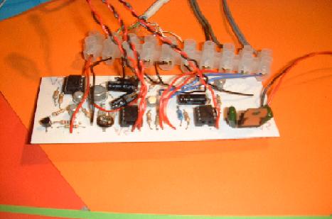
The Main curcuit
This is where most of the operations take place. This board has 3 555 timers that are i.c. that really make it work along with lots of other components.
|
Solder side of main PCB
This is where all the components are attached onto the board. The PCB stands for printed circuit board. |
|
|
|
The control pannel PCB
This one has lots of wires leaving it as they are for all the LED's and the switches. |
Solder side of the control pannel PCB
You can see the blobs of solder conecting the wires to the copper tracks |
|
|
|
Over view of circuit
The 2 PCB's conected together with the long wires that separate the 2 cases. Also the varri board that has the battery back up circuit on. |
Control pannel case
This case is the one u put near the door and has all the switches to set and deset the alarm. It also has most of the LED's. |
|
|
|
The main case
This houses the main PCB the buzz. It has 3 LED's to ack as a deterrent. |
The molds
These molds are made out of wood and are put in the vacuum forming machine to shap the plastic for the cases. |
|
|
|
AS breadboard
This breadboard is not finished yet when a new picture comes availiable it will replace this one. |
My A2 Project, The Lifting Device
To see more on this project click the picture. It will take u to the page which starts with ideas for project. |
|


